

Cable Supports and Accessories

Everything that joins, holds and finishes a CASK cable tray or cable ladder route: splice plates and connectors, dividers and cover clamps, brackets, hangers, strut channels and the bolts, nuts and washers that fix them. Made in our factory in Dilovası, Kocaeli, in the sizes of our trays and ladders and in the same finishes, in accordance with IEC 61537.
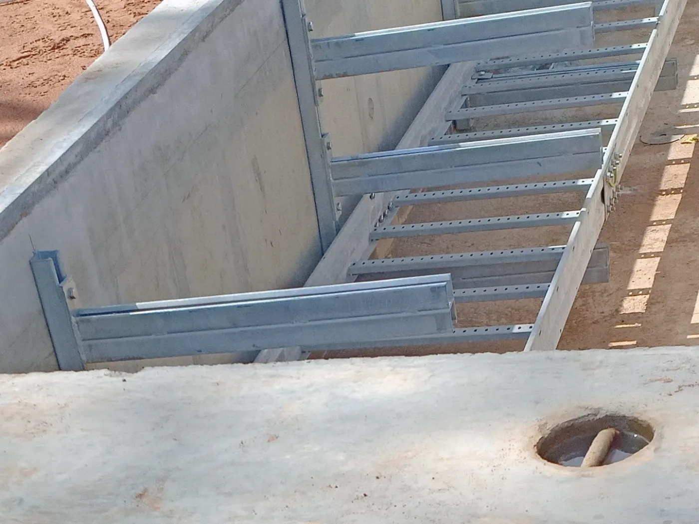
Why the supports matter as much as the tray
A tray or ladder is only as strong as what holds it. The load rating of a cable ladder assumes it sits on supports at the right distance, with its joints close to those supports and fixed with the right plates and bolts. A weak bracket, a joint in the middle of a span or a missing hold-down clamp can lose much of the capacity the tray itself has.
That is why we make the supports and accessories ourselves, matched to each tray and ladder size, in the same steel and finish: the whole route is designed and quoted as one system.
How a support system is chosen
Four questions decide which supports a route needs:
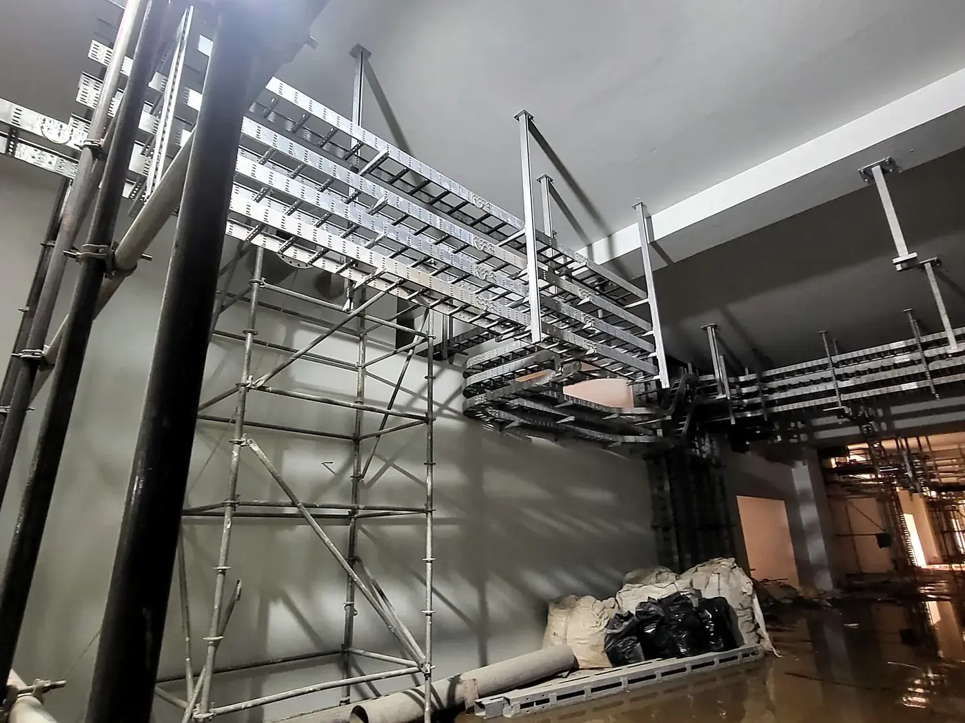
- Where is it fixed? To a wall, the route sits on cantilever brackets fixed with a base plate. From a ceiling, it hangs on threaded rods or hanger posts with a cross channel or bracket underneath. On a floor, trench or structure, it sits on posts or frames made from strut channel.
- How far apart are the supports? This is the span. A shorter span lets the same tray or ladder carry much more, and lets a lighter bracket do the job. Most routes use 1.5 to 3 m.
- How heavy is the load? Add up the weight of the cables per metre (from the cable data sheets), the tray or ladder itself, and a margin for future cables. The bracket must carry this load times the span, at the distance it sticks out from the wall.
- What is the environment? Indoor, outdoor, coastal or chemical sites decide the finish. Use the same finish for the tray, its supports and the bolts.
Strut channel: how much can it carry?
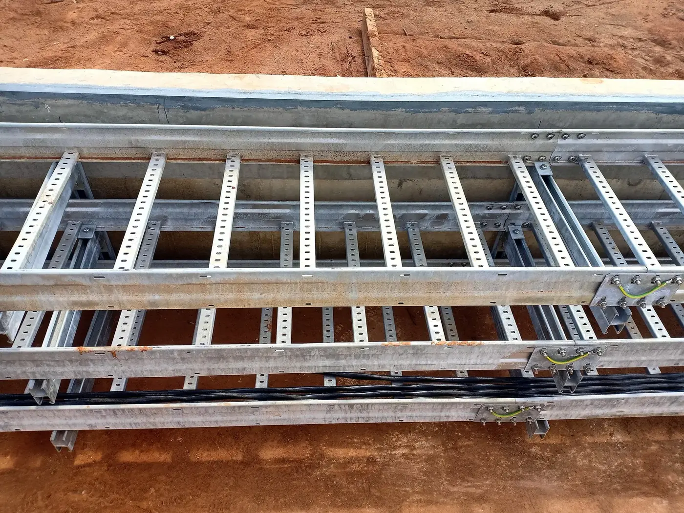
Strut channels (C channels) are the backbone of most support frames: cross arms under hanging routes, posts in trenches, wall rails and cantilever arms. Our channels are in part 3 of the catalogue: single C channel CST-CH004 (19 sizes, W 41 to 128 mm, H up to 120 mm, T 1.5 to 10 mm) and slotted C channel CST-CH007 (31 sizes, 41 x 21 and 41 x 41 mm, T 2.0 to 5.0 mm).
What a channel can carry depends on:
- Span between its own supports. As with trays, the longer the span, the lower the load, and the drop is much faster than the length grows.
- Depth of the profile. A 41 x 41 channel is far stiffer than a 41 x 21 of the same steel; two channels joined back to back are stiffer again.
- Steel thickness. 2.5 mm carries more than 2.0 mm of the same profile.
- Slots. A slotted channel has less steel than a solid one, so it carries somewhat less; it gives fixing points along its whole length.
- How the load is applied. A load spread along the channel is easier to carry than one heavy point in the middle. A cantilever arm carries much less than the same channel supported at both ends.
- How much it may bend. Load ratings are given for a deflection limit, so a channel carrying a cable route does not sag visibly or pull its fixings.
Always check the bolts and anchors too: the fixing is often the weakest point, not the channel.
Joining: splice plates and connectors
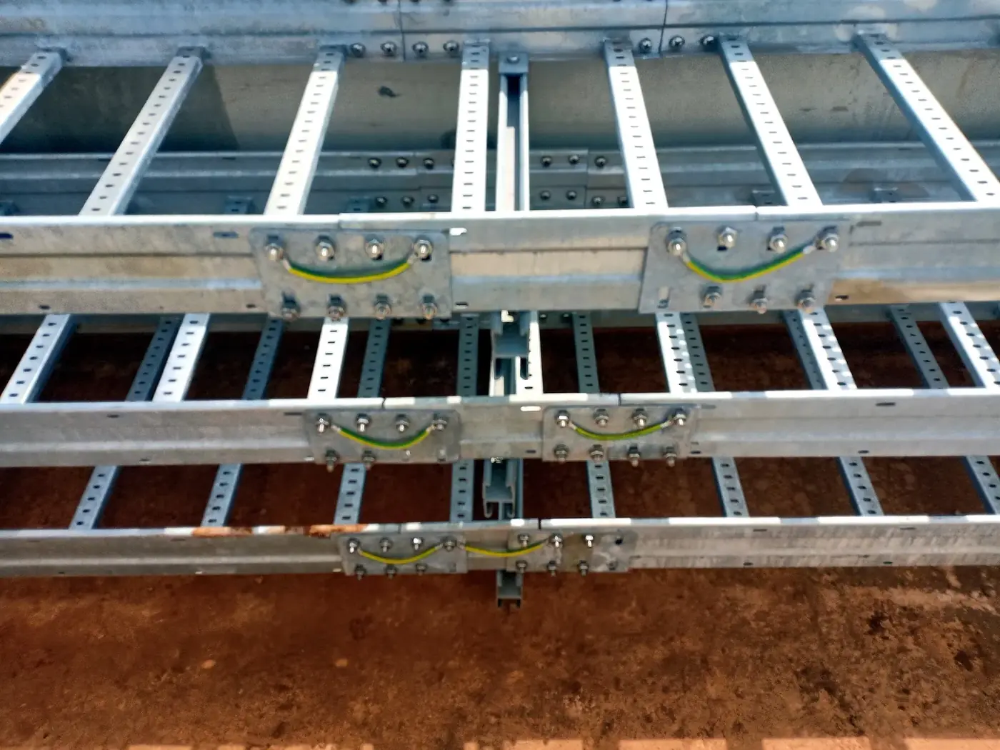
Splice plates join two straight sections or a section and a fitting. They are made in the side heights of our trays and ladders and supplied with matching bolts where listed.
| Product | Base number | Sizes |
|---|---|---|
| Cable tray connector / splice plate | CST-CT053 | 14 sizes, side height 25 to 150 mm, T 1.0 to 2.0 mm, length 230 mm |
| Cable ladder connector / splice plate | CST-CL043 | 4 sizes, T 2.0 mm, side heights 75 and 125 mm |
| Cable tray fish plate | CST-CT106 | 15 sizes, width 50 to 900 mm, T 2.0 to 3.0 mm |
| Cable tray joining plate, for tray with clamping lid | CST-CT130 | 2 sizes |
| Cable ladder coupler, out-flanged ladder | CST-CL083 | 3 sizes, H 100 to 150 mm, T 2.0 mm |
Example: CST-CT053-40-1.5-L230-HDG (tray splice plate for 40 mm side height, 1.5 mm, 230 mm long, hot-dip galvanized).
Changing direction and level: adjustable connectors and hinge plates
Where a fitting is not practical, adjustable connectors let a straight section turn or change level on site.
| Product | Base number | Sizes |
|---|---|---|
| Cable tray horizontal adjustable connector | CST-CT054 | 11 sizes, side height 25 to 150 mm |
| Cable tray vertical adjustable connector | CST-CT055 | 1 size |
| Cable tray hinge connector | CST-CT107 | 9 sizes, side height 25 to 150 mm |
| Cable ladder hinge plate, out-flanged ladder | CST-CL087 | 2 sizes |
Changing width and closing the route
| Product | Base number | Sizes |
|---|---|---|
| Cable tray abrupt reducer plate | CST-CT129 | 45 sizes, width 50 to 300 mm, side height 25 to 150 mm |
| Cable tray drop-out plate (guides cables out of the tray without sharp edges) | CST-CT119 | 10 sizes, width 100 to 900 mm, T 1.5 mm |
| Cable ladder end plate | CST-CL046 | 8 sizes, width 150 to 900 mm, side height 100 and 125 mm |
Separating cables: dividers
Dividers keep power and control cables apart inside one tray, or separate circuits that must not touch.
| Product | Base number | Sizes |
|---|---|---|
| Cable tray divider (straight) | CST-CT108 | 9 sizes, height 25 to 150 mm, T 1.0 to 2.0 mm |
| Cable tray flexible divider (follows bends) | CST-CT109 | 9 sizes, height 25 to 150 mm |
Holding the route: brackets, hangers and base plates
Brackets carry trays and ladders from walls and posts; hangers carry them from ceilings and steel structures.
| Product | Base number | Sizes |
|---|---|---|
| Bracket (cantilever arm), plain and in 41 x 41 strut profile | CST-SP002 | 44 sizes, length 110 to 1,510 mm, T 2.0 to 3.0 mm |
| Base plate | CST-SP001 | 120 x 120 x 5, 150 x 150 x 6, 150 x 150 x 10 mm |
| Hanger post | CST-SP019 | Made to order, length 600 to 6,000 mm |
| Drop-out bracket, out-flanged ladder | CST-SP021 | 3 sizes, H 200 to 300 mm |
| T bracket, out-flanged ladder | CST-SP022 | 3 sizes, H 75 to 125 mm |
| Hanger bracket, out-flanged ladder | CST-SP023 | 3 sizes, H 75 to 125 mm, T 3.0 mm |
| Wall fixing bracket, out-flanged ladder | CST-SP024 | 3 sizes, W 75 to 125 mm, T 3.0 mm |
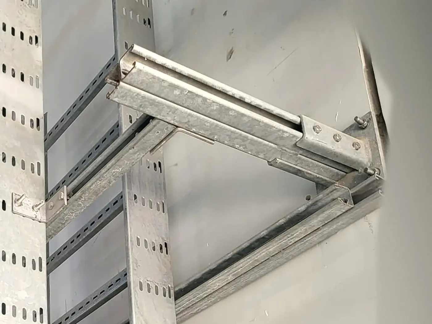
Choose the bracket length to the tray or ladder width plus a little clearance. For heavy routes choose the thicker brackets and keep the span short.
Keeping the route in place: clamps and clips
| Product | Base number | Sizes |
|---|---|---|
| Hold-down clamp (fixes trays and ladders to brackets and channels) | CST-SP011 | 14 sizes, W 25 to 150 mm, T 2.0 and 3.0 mm |
| Ladder hold-down clip | CST-SP020 | 2 sizes, W 30 mm, T 2.0 and 3.0 mm |
| Cable tray slide-in cover clamp | CST-CT117 | 9 sizes |
| Cable tray bolted cover clamp | CST-CT118 | 9 sizes |
Covers are clamped so wind, vibration and maintenance work cannot lift them. Outdoors, use bolted cover clamps.
Fixings: rods, nuts, bolts and washers
| Product | Base number | Sizes |
|---|---|---|
| Threaded rod | CST-FX062 | M8 |
| Spring nut (channel nut) | CST-FX043 | M6, M8, M10, M12 |
| Hex head bolt | CST-FX003 | 10 sizes, M6 x 20 to M12 x 60 |
| Round head bolt (for splice plates) | CST-FX021 | 5 sizes, M6 x 12 to M8 x 20 |
| Hex nut | CST-FX038 | M6, M8, M10, M12 |
| Square nut | CST-FX075 | Made to order, M6 to M14 |
| Flat washer | CST-FX050 | M4, M6, M8, M10, M12 |
Round head bolts are used inside trays and ladders, so their smooth heads do not damage the cable sheaths.
Materials and finishes
Hot-dip galvanized is the standard finish. The finish code is the last part of the part number, the same as on our trays and ladders, so the whole route can be ordered in one finish.
| Code | Finish | Where to use it |
|---|---|---|
| -HDG | Hot-dip galvanized after fabrication, EN ISO 1461 (standard) | Outdoor and industrial sites, C4 |
| -PG | Pre-galvanized strip, EN 10346 (Z275) | Dry indoor areas, C1 to C2 |
| -ZM | Zinc-aluminium-magnesium coated steel, EN 10346 | Severe outdoor and coastal sites, C4 to C5 |
| -EP | Hot-dip galvanized, then epoxy or polyester powder coated | Coastal and chemical sites, C5 |
| -SS304 | Stainless steel AISI 304 | Food and pharma plants, wet indoor areas, C3 to C4 |
| -SS316 | Stainless steel AISI 316L | Offshore, marine and chemical plants, C5 |
Do not mix stainless steel and galvanized parts outdoors: corrosion starts where they touch. Order the tray, its supports and its bolts in the same finish.
Worked example
A cable ladder route, 600 mm wide, runs along a concrete wall indoors, with about 35 kg of cables per metre and supports every 2 m.
- Fixing: wall, so cantilever brackets with base plates: CST-SP002 bracket in 41 x 41 strut profile, 2.5 mm, length 760 mm (ladder width plus clearance), on base plate CST-SP001.
- Load per bracket: 35 kg/m x 2 m span = 70 kg, plus the ladder and a margin for future cables.
- Joints: ladder splice plates CST-CL043 with round head bolts CST-FX021, placed near a bracket, not in the middle of a span.
- Holding: ladder hold-down clips CST-SP020 on every bracket.
- Finish: indoor and dry, so hot-dip galvanized (or pre-galvanized for light duty).
Part numbers: CST-SP002-41-41-2.5-L760-HDG, CST-SP001-002-HDG, CST-CL043-125-2.0-HDG, CST-SP020-30-2.0-HDG.
Summary
| If you need to | Choose |
|---|---|
| Join tray sections | Tray splice plate CST-CT053 or fish plate CST-CT106 |
| Join ladder sections | Ladder splice plate CST-CL043, coupler CST-CL083 for out-flanged ladder |
| Turn or change level without a fitting | Adjustable connectors CST-CT054, CST-CT055, hinge connector CST-CT107 |
| Fix a route to a wall | Bracket CST-SP002 with base plate CST-SP001 |
| Hang a route from a ceiling | Threaded rod CST-FX062 or hanger post CST-SP019 with a channel or bracket |
| Build posts and frames | Strut channel CST-CH004 / CST-CH007 (part 3), spring nuts CST-FX043 |
| Keep trays and covers in place | Hold-down clamp CST-SP011, clip CST-SP020, cover clamps CST-CT117 / CST-CT118 |
| Separate power and control cables | Divider CST-CT108 or flexible divider CST-CT109 |
Frequently asked questions
Are bolts and nuts included with the splice plates and brackets?
Splice plates, connectors and brackets are supplied with matching bolts where the catalogue lists them. Rods, nuts, washers and extra bolts can be ordered as separate lines.
How far apart should the brackets be?
Usually 1.5 to 3 m. The shorter the span, the more the same tray and bracket carry.
Why should joints be close to a support?
A splice plate is weaker than the solid side rail. Load ratings assume the joint sits near a support; a joint in the middle of a span carries much less.
Can a slotted channel carry as much as a solid one?
A little less, because the slots remove steel. In return it gives fixing points along its whole length. For heavy loads choose a deeper or thicker channel, or two channels back to back.
Do your accessories fit other makes of tray?
They are made to the sizes of CASK trays and ladders.
Can I order the supports with the trays?
Yes. Trays, ladders, fittings, supports and fixings are supplied together, in the same finish.
Downloads
Supports and accessories catalogue, part 4 (PDF) · العربية (PDF) · Trunking and channels, part 3 (PDF) · Full cable management catalogue (PDF)
Related products
Questions about this product? Contact us
CASK ELECTRIC © 2026
Factory: Çerkeşli Mah. Tavşancıl Sok. No: 72, Dilovası, Kocaeli
Email: [email protected]